What are the layout principles for an A PILLAR welding fixture?
As a well - established A PILLAR welding fixture supplier, I've had the privilege of working on numerous projects and understanding the intricacies of designing and laying out these fixtures. In this blog, I'll share the key layout principles that are essential for an efficient and effective A PILLAR welding fixture.
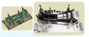
1. Precision and Accuracy
The primary goal of an A PILLAR welding fixture is to hold the A PILLAR components in the correct position with high precision during the welding process. The layout must ensure that all the parts are aligned precisely to meet the design specifications. This means that the fixture should be able to position the components within very tight tolerances, typically in the range of ±0.1mm to ±0.5mm depending on the requirements of the final product.
For example, if the A PILLAR has complex curves and angles, the fixture needs to be designed in such a way that it can accurately replicate these geometries. Any deviation in the positioning of the components can lead to welding defects, such as misaligned joints, uneven weld beads, or poor structural integrity of the final A PILLAR assembly.
To achieve this level of precision, we often use high - quality linear guides, precision locators, and adjustable stops in the fixture layout. These components help in accurately positioning and clamping the A PILLAR parts, ensuring that they remain in place throughout the welding process.
2. Accessibility for Welding
Another crucial layout principle is to ensure easy accessibility for the welding equipment. Welders need to have unobstructed access to the welding joints to perform their tasks efficiently. The fixture should be designed in a way that allows the welding torch to reach all the necessary welding points without any interference.
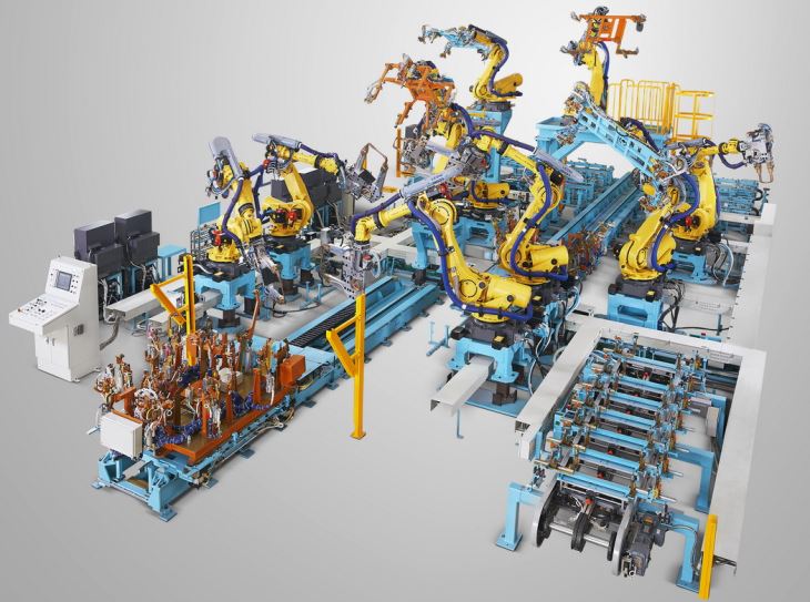
In the case of robotic welding, the layout must consider the range of motion of the robot arm. The fixture should be arranged so that the robot can move freely around the A PILLAR components and perform welding operations at different angles. This may involve creating open spaces or recesses in the fixture design to accommodate the robot's movement.
For manual welding, the layout should provide enough space for the welder to comfortably hold the welding gun and access the joints. Adequate clearance should be maintained around the welding areas to prevent any accidental contact with the fixture, which could cause damage to the equipment or affect the quality of the weld.
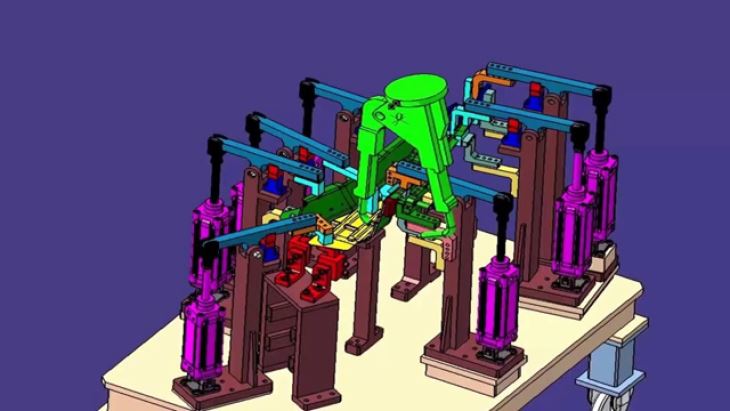
3. Stability and Rigidity
The A PILLAR welding fixture must be stable and rigid enough to withstand the forces generated during the welding process. Welding involves high - temperature heat input and mechanical forces, which can cause the fixture to vibrate or deform if it is not properly designed.
A stable fixture layout starts with a solid base structure. The base should be made of heavy - duty materials, such as steel or cast iron, to provide a stable foundation for the entire fixture. All the components of the fixture, including the locators, clamps, and supports, should be firmly attached to the base to prevent any movement or displacement.
In addition, the fixture should be designed to distribute the welding forces evenly across its structure. This can be achieved by using a well - balanced layout and proper reinforcement in critical areas. For example, if the A PILLAR has a large surface area, additional supports may be required to prevent it from sagging or warping during welding.
4. Flexibility and Adaptability
In today's manufacturing environment, there is often a need to produce different variants of A PILLARS. Therefore, the fixture layout should be flexible and adaptable to accommodate these changes.
One way to achieve flexibility is by using modular design concepts. The fixture can be divided into smaller, interchangeable modules that can be easily replaced or reconfigured to suit different A PILLAR designs. This allows for quick changeovers between different production runs, reducing downtime and increasing productivity.
Adjustable components, such as adjustable locators and clamps, can also be incorporated into the fixture layout. These components can be adjusted to accommodate minor variations in the A PILLAR dimensions, ensuring that the fixture can be used for a wider range of products.
5. Safety
Safety is of utmost importance in any manufacturing process, and the layout of the A PILLAR welding fixture is no exception. The fixture should be designed in a way that minimizes the risk of accidents and injuries to the operators.
This includes providing proper guarding around the moving parts of the fixture, such as clamps and actuators. The guarding should prevent the operators from accidentally coming into contact with these parts during the welding process. In addition, the fixture should be designed to prevent any hot metal spatter or fumes from escaping and causing harm to the operators.
Proper lighting and ventilation should also be considered in the fixture layout. Good lighting ensures that the operators can clearly see the welding joints, reducing the risk of errors. Adequate ventilation helps in removing the welding fumes, which can be harmful if inhaled.
6. Ease of Maintenance
A well - designed A PILLAR welding fixture should be easy to maintain. The layout should allow for easy access to all the components of the fixture for inspection, cleaning, and replacement.
Components that are prone to wear and tear, such as locators and clamps, should be easily removable and replaceable. This reduces the downtime required for maintenance and ensures that the fixture can be quickly returned to service.
In addition, the fixture should be designed in a way that allows for easy cleaning. Welding residue and debris can accumulate on the fixture over time, which can affect its performance. By providing easy access to all the surfaces of the fixture, it becomes easier to clean and maintain.
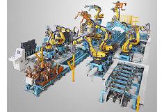
7. Integration with Other Systems
In modern manufacturing, the A PILLAR welding fixture often needs to be integrated with other systems, such as conveyor systems, robotic welding cells, and quality control systems. The layout of the fixture should be designed to facilitate this integration.
For example, if the A PILLAR is transported to the welding fixture using a conveyor system, the fixture should be positioned in such a way that it can easily receive the components from the conveyor. The interface between the fixture and the conveyor should be designed to ensure smooth and accurate transfer of the A PILLAR parts.
In the case of integration with robotic welding cells, the fixture layout should be compatible with the robot's programming and control system. The fixture should provide the necessary signals and feedback to the robot to ensure proper operation.
If you're interested in learning more about our Auto Pillar Parts Welding Fixture or Robotic Welding Fixture Line, we encourage you to reach out to us for a detailed discussion on your specific requirements. We are committed to providing high - quality welding fixtures that meet the highest standards of precision, efficiency, and safety. Contact us today to start a productive conversation about your A PILLAR welding fixture needs.
References
- "Welding Fixture Design Handbook", Industrial Press Inc.
- "Automotive Body Welding Technology", Society of Automotive Engineers (SAE)