As a supplier of Robotic MIG Weld Fixtures, I've witnessed firsthand the critical role that properly adjusted welding parameters play in achieving high - quality welds. In this blog, I'll share some insights on how to adjust the welding parameters on a Robotic MIG Weld Fixture.
Understanding the Basics of Robotic MIG Welding
Metal Inert Gas (MIG) welding is a popular welding process in which an electric arc forms between a consumable wire electrode and the workpiece metal. This arc generates heat, melting the wire and the base metal, which then fuses together to create a weld. A robotic MIG weld fixture automates this process, offering greater precision, consistency, and productivity compared to manual welding.
Key Welding Parameters
Before delving into the adjustment process, it's essential to understand the key welding parameters involved in MIG welding:
- Wire Feed Speed (WFS): This refers to the rate at which the welding wire is fed into the weld pool. A higher WFS generally results in more heat input and a larger weld bead, while a lower WFS may lead to a smaller bead and less heat.
- Voltage: Voltage controls the length of the electric arc. Higher voltage creates a longer arc, which can increase the heat input and the width of the weld bead. Lower voltage shortens the arc and can result in a more concentrated heat source.
- Travel Speed: It is the speed at which the welding torch moves along the joint. A faster travel speed reduces the heat input per unit length, resulting in a narrower and shallower weld bead. A slower travel speed increases the heat input and produces a wider and deeper bead.
- Shielding Gas Flow Rate: Shielding gas protects the weld pool from atmospheric contamination. The appropriate flow rate depends on factors such as the type of shielding gas, welding current, and the environment.
Adjusting the Welding Parameters
Step 1: Analyze the Workpiece
The first step in adjusting the welding parameters is to analyze the workpiece. Consider the material type (e.g., steel, aluminum), thickness, and joint design. Different materials have different melting points and thermal conductivities, which will affect the welding process. For example, aluminum has a lower melting point and higher thermal conductivity than steel, so it may require different welding parameters.
Step 2: Start with Manufacturer Recommendations
Most Robotic MIG Weld Fixtures come with manufacturer - recommended welding parameters based on common materials and thicknesses. These recommendations can serve as a starting point. You can find these guidelines in the user manual or on the manufacturer's website. For instance, if you are welding 3 - mm thick mild steel, the manufacturer might suggest a specific wire feed speed, voltage, and travel speed combination.
Step 3: Conduct Test Welds
Once you have the initial parameter settings, conduct test welds on a sample piece of the same material and thickness as the actual workpiece. Observe the appearance of the weld bead, including its width, penetration, and shape. Check for any signs of defects such as porosity, undercutting, or lack of fusion.
- Wire Feed Speed and Voltage Adjustment: If the weld bead is too narrow and has poor penetration, you may need to increase the wire feed speed and/or voltage. Conversely, if the weld bead is too wide and has excessive spatter, you might need to decrease these parameters.
- Travel Speed Adjustment: If the weld bead is too tall and has a convex shape, the travel speed may be too slow. Increasing the travel speed can result in a flatter and more uniform weld bead. If the weld bead is too shallow and has poor fusion, the travel speed may be too fast.
Step 4: Fine - Tuning the Parameters
After the initial test welds, fine - tune the parameters based on the results. Make small adjustments to one parameter at a time and conduct additional test welds to evaluate the changes. This iterative process allows you to optimize the welding parameters for the specific application.
- Shielding Gas Flow Rate: If you notice porosity in the weld, it could be due to insufficient shielding gas. Increase the flow rate slightly and check if the porosity improves. However, excessive flow rate can cause turbulence and also lead to porosity.
Importance of Monitoring and Documentation
Once you have determined the optimal welding parameters, it's crucial to monitor the welding process regularly. Use sensors and monitoring systems available in modern Robotic MIG Weld Fixtures to ensure that the parameters remain within the specified range. Any deviation from the set parameters can lead to inconsistent weld quality.
Documentation is also essential. Keep a record of the welding parameters used for each workpiece or job. This documentation can be useful for future reference, quality control, and troubleshooting.
Special Considerations for Different Applications
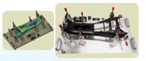
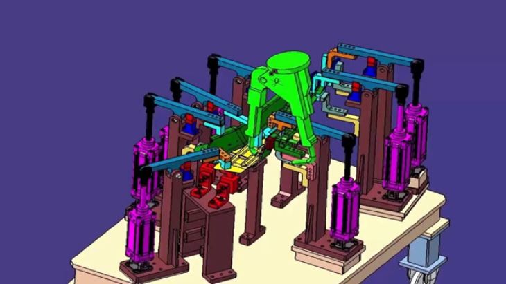
Auto Pillar Parts Welding Fixture
For applications involving Auto Pillar Parts Welding Fixture, precision is of utmost importance. The pillars are critical structural components in an automobile, and the welds need to be strong and defect - free. Adjust the welding parameters to ensure proper penetration and fusion, especially in areas where the joints are complex. You may need to use a lower travel speed and higher wire feed speed to achieve the desired weld quality.
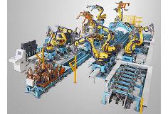
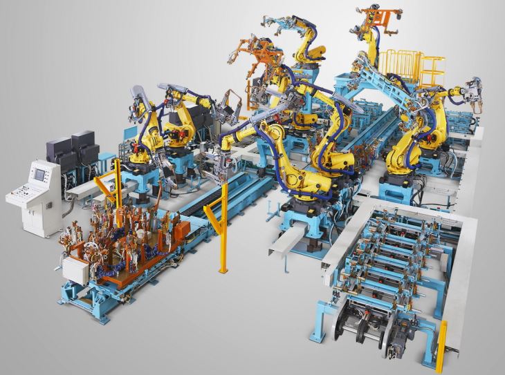
Robotic Welding Fixture Line
In a Robotic Welding Fixture Line, where multiple workpieces are welded in a continuous process, consistency is key. Set up the welding parameters to ensure that each weld on every workpiece meets the same quality standards. Regularly calibrate the robots and monitoring systems to maintain the accuracy of the welding process.
Conclusion
Adjusting the welding parameters on a Robotic MIG Weld Fixture is a complex but essential process. By understanding the key parameters, analyzing the workpiece, starting with manufacturer recommendations, conducting test welds, and fine - tuning the settings, you can achieve high - quality welds. Special considerations for different applications such as auto pillar parts and robotic welding fixture lines ensure that the specific requirements of each job are met.
If you are in the market for a Robotic MIG Weld Fixture or need further assistance with welding parameter adjustment, we are here to help. Our team of experts can provide you with personalized solutions and support to optimize your welding process. Contact us to start a procurement discussion and take your welding operations to the next level.
References
- AWS Welding Handbook, Volume 1: Welding Science and Technology, American Welding Society.
- Welding: Principles and Applications, Larry Jeffus.